
Field Testing & Verification Blower-Door and Duct-Leakage Verification
Tacoma Energy provides coordinated blower-door and duct-leakage testing for residential projects. Measured results help builders document compliance, identify performance concerns, and confirm that the building enclosure and HVAC distribution system are ready for project closeout.
Measured Performance
Calibrated testing replaces visual assumptions with documented results for whole-home air leakage and HVAC distribution-system leakage.
Construction Quality
Testing helps identify whether enclosure and duct performance align with project targets and whether corrective work or retesting may be needed.
Clear Documentation
Results support applicable energy-code, ERI, ENERGY STAR®, certification, builder, and final project documentation requirements.
Two tests. Two different parts of home performance
Blower-door testing evaluates the building enclosure. Duct-leakage testing evaluates the HVAC distribution system. Together, they provide a clearer picture of installed performance.
Blower-Door Testing
A calibrated fan creates a controlled pressure difference across the building enclosure so unintended whole-home air leakage can be measured.
Duct-Leakage Testing
Calibrated testing measures air escaping through duct connections, seams, boots, plenums, and other parts of the HVAC distribution system.
How whole-home air leakage is measured
The test creates a controlled pressure difference so air movement through unintended openings in the building enclosure can be measured using standardized equipment.
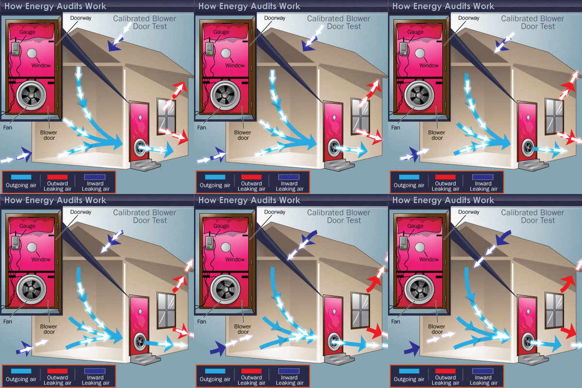
Blower-Door Testing
A calibrated fan changes the pressure inside the home so leakage through the enclosure can be measured and documented.
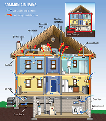
Common Air-Leakage Pathways
Leakage can occur at walls, ceilings, floors, windows, doors, attic access points, plumbing and electrical penetrations, and mechanical connections.
What an illustrative duct-leakage volume can represent
The example below is retained from the original duct-leakage page to show the scale of conditioned-air volume associated with its illustrative calculation.
One day of illustrative leakage equals the indoor air volume of a typical 2,000-square-foot home more than 13 times.
Visual comparison assumes a 2,000-square-foot conditioned home with uniform 8-foot ceilings. It compares total volume only and does not represent the measured air-change rate of a specific home.
These values represent the original page’s example calculation using 10% duct leakage. Actual leakage and energy impact vary by home, system, operating conditions, climate, and construction quality.
From scheduling through documented results
Testing scope and timing are coordinated around construction status, applicable targets, and project documentation requirements.
Confirm the testing scope
Construction stage, applicable targets, system count, site readiness, and documentation requirements are reviewed before the visit.
Complete field testing
The enclosure, duct system, or both are prepared and tested using calibrated equipment and standardized procedures.
Document results and next steps
Measured results are recorded for the builder and compliance team, with correction or retesting needs identified when applicable.
Need field testing coordinated across plans or communities?
Share the project location, construction stage, and applicable requirements. Tacoma Energy will help confirm the testing scope and next steps.
Start a Project